The demodulation of single-sideband (SSB) signals requires special attention, because simple mixing leads to superposition of the upper and lower sidebands at audio frequencies. The following article gives an overview of the different methods for SSB demodulation and their use in software defined radios. SSB modulators and demodulators are sometimes also referred to as image reject mixers.
1. The Filter Method (Superhet)
The filter method is the traditional SSB reception method in analog superhet receivers. Typically a first mixer translates the signal to an intermediate frequency (IF) first. At the IF a sharp band-pass filter with fixed frequency response simply selects only one of the two sidebands and suppresses the other one. Then the second mixer converts the remaining sideband to audio frequencies. If required, the audio spectrum can be inverted by using high-side local oscillator injection in one of the mixer stages.
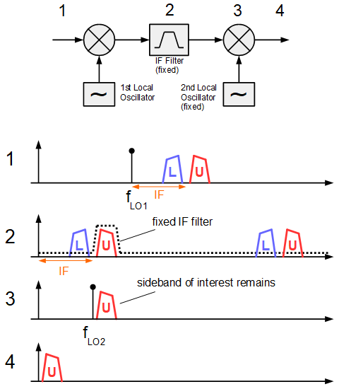
The filter method requires the availability of very sharp filters at the IF and is widely spread in the analog domain, where quartz filters are used. Sideband suppression is determined by the sharpness and attenuation of the filter for the unwanted sideband.
2. The Phasing Method (Direct Conversion)
The phasing method uses complex IQ processing to resolve the superposition of lower and upper sideband at audio frequencies. The complex mixer directly converts the incoming signal to audio frequencies ands creates I and Q components (zero-IF or direct conversion receiver). The complex mixer stage consists of a a sine and cosine local oscillator (e.g. implemented by a phase shift of 90°) and two mixers. The following low-pass filters with a width of one sideband determines the final bandwidth. After filtering a Hilbert transformer shifts the Q component by 90° before it can be added or subtracted to the I component to select one of the two sidebands.
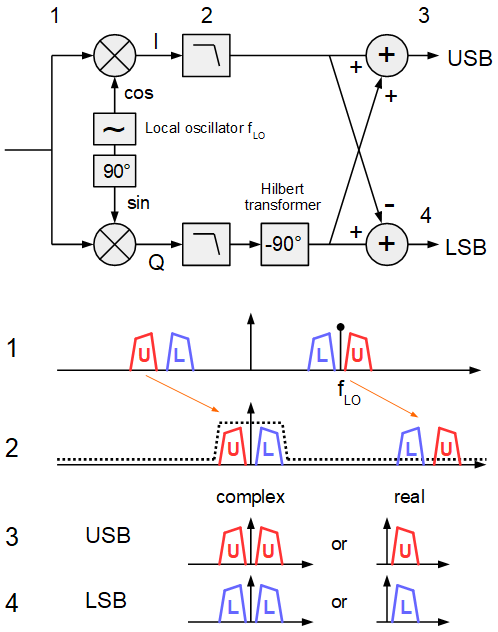
To realize acceptable sideband suppression, the 90° phase shift for the LO and the 90° shift between I and Q, as well as their amplitude have to be matched exactly. This is hardly practical with analog components. However in the digital domain, the LO phase shift can easily be realized by a sine and cosine look-up table. Also amplitude variations are not a problem in digital processing, if the 90° phase shift for Q is distributed between both I and Q path with a 45° and -45° phase shifter. This makes the phasing method interesting for implementation in a software defined radio.
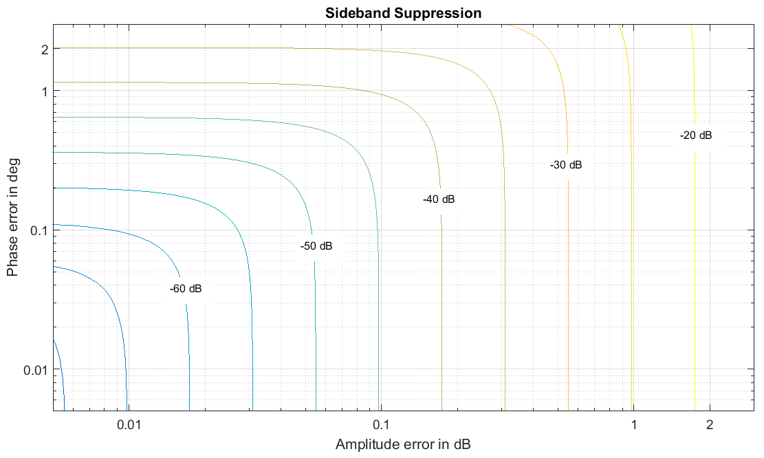
The only drawback is the exact implementation of the 45° phase shifts. Even with a digital filter it is hard to achieve an accurate and constant shift of 45° over all audio frequencies. In practice already small phase deviations lead to prohibit very good sideband suppression, especially for frequencies at the frequency borders of the sidebands.
Further reading for the phasing method:
- Rick Lyon’s in-depth tutorials “Understanding the ‘Phasing Method’ of Single Sideband Demodulation” and the more general “Quadrature Signals: Complex, but not complicated”.
- Ken Martin’s comprehensive paper on IQ demodulation: Complex Signal Processing is Not — Complex
- For a non-complex introduction to the phasing method and analog circuit considerations: Wes Hayward’s book “Experimental Methods in RF Design”, ARRL, 2009
- On the design of Hilbert and all-pass filters for phase shifting: “Hilbert Transform Filters, and Other Phase Adjusted Band Pass Filters”.
3. The Weaver Demodulator (The “Third Method”)
The Weaver demodulator (also called the “Third Method”, besides filtering and phasing techniques) for SSB reception has been introduced by D. Weaver in “A Third Method of Generation and Detection of Single-Sideband Signals”. It differs a little bit from the first two methods since it does not resolve any superposition of lower and upper sideband. Instead the Weaver simply converts a portion of the spectrum to audio frequencies without any ambiguities. The Weaver demodulator uses two complex mixing stages. The first mixer stages translates the signal in order to center the wanted sideband at zero frequency. There the bandwidth is selected by low-pass filters with half the bandwidth of a sideband (f_{edge} = BW_{SSB} / 2 ) . A second mixer stage translates the signal in order to align its frequencies with the audio frequencies. Summing or subtracting I and Q selects the orientation of the output spectrum (normal or inverted).

The Weaver method is very well suited for software defined radios, because digital mixers and their sine and cosine LO signals can be generated with extremely high phase and amplitude accuracy. The same holds for the two identical low-pass filters. Thus no gain and phase variations occur and the circuit is perfectly balanced for very high performance.
Further reading on the Weaver demodulator:
- D. Weaver’s original paper: “A Third Method of Generation and Detection of Single-Sideband Signals”
- Ken Martin’s comprehensive paper on IQ demodulation: Complex Signal Processing is Not — Complex
4. Fourier based Demodulation
The Fourier approach follows a very intuitive approach: The idea is to simply select the wanted sideband and supress all other signals with a flexible filter prior to down-conversion. This is usually not feasible in the analog domain, because analog filters mostly have a fixed frequency response. However digital signal processing can apply very flexible filtering with almost every frequency response in the spectral (Fourier) domain.
The basic concept of Fourier based demodulator is as follows: It first calculates the signal’s spectrum with a FFT. Then in the spectral domain all frequency bin are set to 0 that do not belong to the sideband of interest. After that the bins are shifted to audio frequencies. Finally an inverse FFT converts the FFT spectrum back to a time signal.
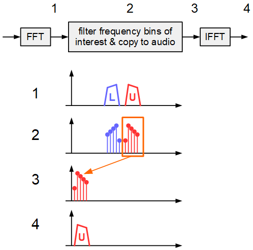
In practice this approach is slightly more challenging: The FFT needs to process the signal stream blockwise (block by block). Simply setting frequency bins to zero leads to aliasing in the time domain blocks at the output. This is because this zero forcing works like a filter with perfectly rectangular shape. However rectangular filters have a infinite impulse response in the time domain, which cannot be mapped to blocks of finite length. Therefore a better idea is to replace the zero forcing of bins with the application of a FIR filter shape, that has a finite length time response (FIR = finite impulse response). Details on the blockwise processing of FFT and filtering in the spectral domain can be found under the terms overlap-and-add or overlap-and-save.
A big advantage of the fourier based demodulation is, that multiple down converters can easily be implemented in parallel. This enables SDR operation for many users at the same time. The well-known Twente WebSDR (more than 2000 parallel users) also works that way.
Further reading on Fourier based demodulation and down conversion:
- Phil Harman’s presentation on Direct Fourier Conversion
- Andras Retzler’s FastDDC
- Mark Borgerding’s in-depth paper: Turning Overlap-Save into a Multiband Mixing, Downsampling Filter Bank
5. Further Methods
Further methods for SSB demodulation are possible, though quite exotic. Some rely on the fact that any modulation type can be considered as a superposition of amplitude and phase/frequency modulation, e.g. in “Innovative demodulation method for SSB technique“. This method does not use any mixers. But it requires a small modulation index and suffers from poor sideband suppression and distortions due to nonlinearities. Therefore its practical relevance is somehow limited.


